 |
www.elektronik.si
Forum o elektrotehniki in računalništvu
|
| Poglej prejšnjo temo :: Poglej naslednjo temo |
| Avtor |
Sporočilo |
Silvo
Moderator


Pridružen-a: Pon 24 Feb 2003 17:09
Prispevkov: 14673
Aktiv.: 61.94
Kraj: Koroška-okolica Dravograda
|
 Objavljeno: Pon Feb 05, 2007 9:35 pm Naslov sporočila: Objavljeno: Pon Feb 05, 2007 9:35 pm Naslov sporočila: |
 |
|
| _ID_ je napisal/a: |
| A lahko kdo prosim poskusi "zapečt" ta program in poroča če je dober. Avtor trdi da naj bi bil. |
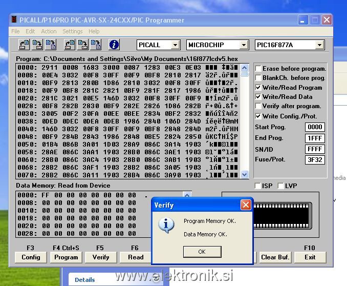
Čip se sprogramira normalno. Tole sem sicer programiral s PICALLW (verzija hardwera v katerem je pic) - imam ga namreč ravno na kablu.
_________________
lp
Silvo |
|
| Nazaj na vrh |
|
 |
ID
Član

Pridružen-a: Pet 17 Jun 2005 18:17
Prispevkov: 865
Aktiv.: 3.65
Kraj: Ljubljana-Podpeč
|
| Objavljeno: Pon Feb 05, 2007 10:19 pm Naslov sporočila: |
|
|
| Hvala, Silvo. Torej je napaka nekje na hardveru ali pa v softveru. Po moje je problem slednje, glede na to, da mi v drubem programu sprogramira ostala pva PICa brez problema. Bom še malo prebrskal po programu, čeprav se mi niti ne sanja kaj bi lahko bilo narobe.
|
|
| Nazaj na vrh |
|
|
ID
Član
Pridružen-a: Pet 17 Jun 2005 18:17
Prispevkov: 865
Aktiv.: 3.65
Kraj: Ljubljana-Podpeč
|
| Objavljeno: Sob Mar 17, 2007 9:11 pm Naslov sporočila: |
|
|
| Končno mi je uspelo usposobiti programator! Sedaj brez problema programira vse pice. Dodatnega upora med Vpp2 in minus nisem vstavljal in brez problema sprogramira tudi 16F877A! Edino prog delay sem mogel nastaviti na 5. Končno imam tudi jaz en spodoben programator! Silvo še enkrat hvala za trud! Brez tvoje pomoči se verjetno nebi lotil odpravljanja napak!
|
|
| Nazaj na vrh |
|
|
Dadi
Član
Pridružen-a: Čet 24 Jan 2008 20:45
Prispevkov: 50
Aktiv.: 0.24
Kraj: Prevalje
|
| Objavljeno: Čet Apr 17, 2008 10:05 am Naslov sporočila: Pic16pro |
|
|
Izdelal sem še ta programator (pic16pro) s 74ls05. PCB je iz avtorjeve strani. Imam pa problem s software-om. S PICALL 0.16 lahko normalno sprogramiram 16F877A, ne morem pa usposobiti Winpic programerja. Ko zaženem WINPIC se LEDice na programatorju prižigajo in ugašajo, spreminja se jakost,... Ko dam programirat, traja nekaj časa, sveti LED za programiranje, pri verificiranju pa javi napako. Nisem pa testiral s kakim drugim PICem.
_________________
Damjan |
|
| Nazaj na vrh |
|
|
Silvo
Moderator
Pridružen-a: Pon 24 Feb 2003 17:09
Prispevkov: 14673
Aktiv.: 61.94
Kraj: Koroška-okolica Dravograda
|
| Objavljeno: Čet Apr 17, 2008 1:45 pm Naslov sporočila: |
|
|
Dadi,
Naredi si svojo konfiguracijsko datoteko. Konfiguracijske datoteke se nahajajo v mapi "interfaces". (najbolje eno že obstoječo prekopirat pod drugo ime ter spremetiti potrebne nastavitve) Navodilo kaj kaj pomeni najdeš v helpu.
Copy/paste:
Adapting WinPic for other (simple) programming interfaces
If your (simple) programmer for the parallel or serial port is not listed on the 'interface' tab, here's what to do:
Copy and rename one of the SampleInterfaceXXX.INI in the 'interfaces' subdirectory (part of the installation package) into another file, for example MyInterface.INI
With your favorite text editor, load 'your' interface definition file and modify it for your needs. There is a section
[ProgrammerControlLines]
with the following entries ... some of them optional, only a few are mandatory, marked with "m"=mandatory:
DataIn (m)
serial data line from PIC to PC. Example for a simple interface on the serial port:
DataIn=cts
OkButton
signal from programming adapter to PC for an optional "OK"-button.
VppOnOff (m)
control line to turn the programming voltage on(H) and off(L). From PC to PIC. Example for a simple interface:
VppOnOff=txd
VddOnOff
control line to turn the supply voltage on(H) and off(L). From PC to PIC.
PullMclrDown
control line to pull the MCLR pin down to ground. As far as I know, only Microchip's "AN589"-programmer uses this (with PullMclrDown=D4)
Connect
control line to connect(H) or disconnect(L) the target. From PC to programming interface. Usually "!D7".
ClockOut (m)
serial clock output from PC to PIC. Example for a simple interface on the serial port:
ClockOut=rts
DataOut (m)
Definies the interface signal which is used to send serial data output from PC to PIC. Example for a simple interface on the serial port:
DataOut=dtr
DataOutWhileReading
Defines the logic state (not a control signal) of the data output line while reading. For most interfaces, the data output must be set to a logic "1" by the programmer, so the PIC can pull the serial output low (because most interfaces use an NPN-transistor or open collector output stage, and a pullup resistor connected to Vdd). For interfaces with a tristate output, the level of the serial ouput line while reading doesn't matter (use "OutEnable" to define the control line for the tristate driver in that case). Example for a simple interface on the serial port:
DataOutWhileReading=1
ClkEnable
Tristate buffer control for the serial clock output. As far as I know, the only interface which uses this is the original Microchip "AN589" programmer. "H" level means output enabled (from PC to PIC), "L" means output disabled (high impedance). Example for a simple interface:
ClkEnable=nc
OutEnable
Tristate buffer control for the data output. As far as I know, the only interface which uses this is the original Microchip "AN589" programmer. "H" level means output enabled (from PC to PIC), "L" means output disabled (high impedance).
RedLed
Optional output from the PC to a red LED on the programmer, signalling "error state" after programming.
GreenLed
Optional output from the PC to a green LED on the programmer, signalling "success" after programming.
The function token in the definition file is followed by a "=" character, and a symbolic definition for the control signal which is used. This can be any of the centronics data lines, inverted (LOW-active) or not inverted (HIGH-active). "Active" must be seen from the target's point of view. If -for example- there is an inverter between the serial data output on centronics D0 and the PIC's "RB7" pin, the definition line must be
DataOut=!D0
which means
"The serial data output is connected to D0, inverted" (the '!' character to invert something is "C"-style)
These names can be used for control lines on the centronics port ("LPT1" or "LPT2"). Non-inverted always means active-HIGH level on the PC's output, no matter what the centronics printer specification says (signals which are inverted by the PC hardware are automatically inverted by software !).
D0, D1, ... D7
centronics data, not inverted. Can be used as OUTPUTS from PC to target.
!D0, !D1, ... !D7
centronics data, inverted. Can be used as OUTPUTS from PC to target.
pap, !pap
centronics "paper out", normal (H=active) or inverted (L=active). Can be used as INPUT from target to PC.
ack, !ack
centronics "acknowledge", normal (H=active) or inverted (L=active). Can be used as INPUT from target to PC.
str, alf, psl, ini
Other control signals OUTPUTS from PC to target: strobe, automatic line feed, select printer, initialize printer(reset).
bsy, sld, err
Other INPUTS from target to PC: busy, selected, error
nc
not connected. Use this token for all unused/unsupported functions, like "RedLed=nc" . All unused functions appear disabled on the "Interface Test" tab.
For an interface on the serial port, these control lines are available (may be used if you have an interface with an inverting RS-232 level converter like the MAX232). If you use the original "COM84" programmer, you don't have to write your own interface definition !
txd, !txd
Transmit Data (here: abused as simple control line). For COM84, "txd" is used as programming voltage (non-inverted)
dtr, !dtr
Data Terminal Ready. For COM84, "dtr" is used as serial data output from PC to PIC (non-inverted)
rts, !rts
Ready To Send. For COM84, "rts" is the serial clock output from PC to PIC.
cts, !cts
Clear To Send. For COM84, "cts" is the serial data input (from PIC to PC).
Other "control signal tokens" are listed in the LPT connector table, or in the SampleInterfaceXXX.INI files. Every macro definition can control up to 4 output lines, like:
SelVddHigh=D0+D1+!D2+!D3
which will set both D0+D1 high and D2+D3 low when the supply voltage shall generator shall be configured for "high supply voltage (see notes on simple production-grade programmers).
If you have the source code of WinPic, look for "PicHw_TokenToInOutFunc()" to find out which tokens are implemented so far 
To continue the installation of a customized programming interface...
Save your modified interface definition file (interfaces\MyInterface.INI) now, and close the text editor.
Open WinPic's "Interface" tab and select "Custom , on XXX port, defined by file" (XXX = COM or LPT; scroll to the end of the list !).
Notice that the edit field under "Custom interface definition file" will be enabled now.
Enter the name of your interface definition file in the edit field, or click "Select" to open a file selector.
Note: THE INTERFACE DEFINITION FILE MUST BE IN THE 'interfaces' SUBDIRECTORY !
If an error message like "invalid signal definition" appears, check your interface definition file again (with a text editor) and try again.
If everything is ok, check the proper function of the control lines with the interface test option. Keep your interface definition file in WinPic's directory, because this file will be loaded whenever you start the program again (the definitions are NOT copied into the SETTINGS.INI file. Only the name of your interface definition file is saved in the settings !)
Pred časom sem naredil še prevod- glavnih menujev v slovenščino. Priloženo datoteko skopiraš v mapo "translations", ter jo izbereš v zavihku "setings".
| Opis: |
|

Download |
| Ime datoteke: |
slov.zip |
| Velikost datoteke: |
6.83 KB |
| Downloadano: |
18 krat |
_________________
lp
Silvo |
|
| Nazaj na vrh |
|
|
Dadi
Član
Pridružen-a: Čet 24 Jan 2008 20:45
Prispevkov: 50
Aktiv.: 0.24
Kraj: Prevalje
|
| Objavljeno: Čet Apr 17, 2008 9:25 pm Naslov sporočila: |
|
|
Sem usposobil zadevo. Če bo kdo imel podobne težave sta tu dve ini datoteki. Ena za 40 pinske in ena za ostale.
| Opis: |
| Dve ini datoteki za P16PRO s 74LS05 |
|
Download |
| Ime datoteke: |
ini.zip |
| Velikost datoteke: |
696 Bytov |
| Downloadano: |
13 krat |
_________________
Damjan |
|
| Nazaj na vrh |
|
|
|
|
Ne, ne moreš dodajati novih tem v tem forumu
Ne, ne moreš odgovarjati na teme v tem forumu
Ne, ne moreš urejati svojih prispevkov v tem forumu
Ne, ne moreš brisati svojih prispevkov v tem forumu
Ne ne moreš glasovati v anketi v tem forumu
Ne, ne moreš pripeti datotek v tem forumu
Ne, ne moreš povleči datotek v tem forumu
|
Uptime: 493 dni
Powered by phpBB © 2001, 2005 phpBB Group
|


